Em Lock System Wiring Diagram
Two single doors with panic bars. Inspect the frame header to determine if mounting accessories are required (refer to page 4).
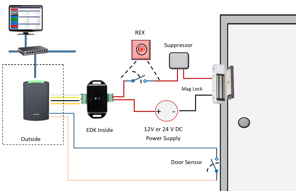
External Mag Lock Wiring Diagram / Solve The Problem
Fold template as indicated on dotted line.

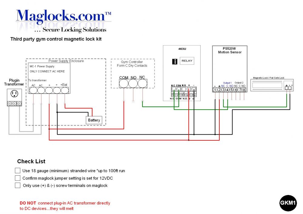
Em lock system wiring diagram. Magnetic lock wiring diagram much like the door access control system diagram above, the mag lock wiring diagram relies on a few simple basics: 3 select the type of door lock to use, no type or nc type. If this is not available you may use an ac power source and wire inline a "full wave bridge" rectifier.
End block (with screw holes) magnet end block wiring cover spacer board front side of lock a. Rotate board 180°, then reassemble. Count the led blinks after turning it.
There are two types of diagrams. Lever locks for fire doors. Note the hole on the side of the magnetic lock for wires to pass through.
Two single doors with panic bars. Depending on the system used, the dry contacts will be located in the master unit or the door station. Remove screws, wiring cover and end blocks.
Within bs en 60204 there are references to other standards including bs en 60947. The block diagram of the access control system is shown in fig. Make sure that actuator will not block other moving parts inside of door (screen and its mechanism).
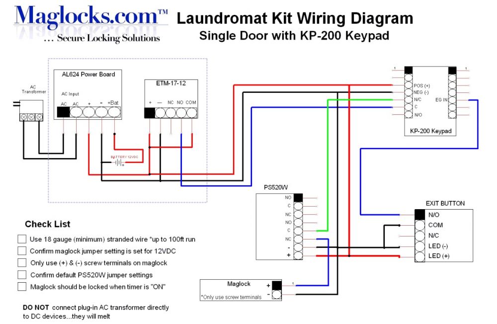
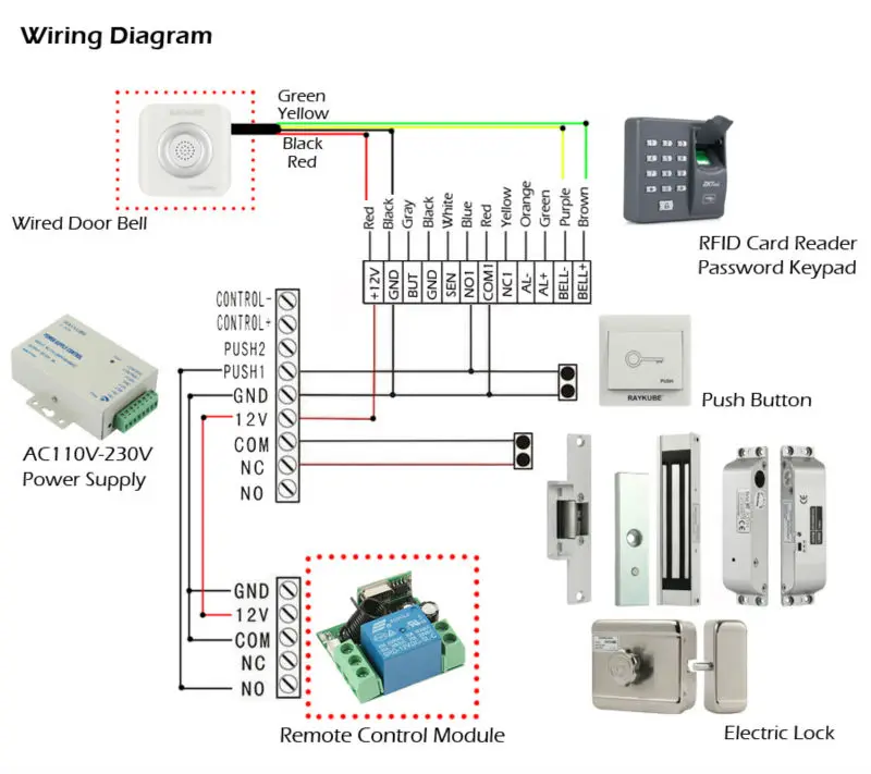
A well defined wiring diagram considerably reduces the wiring efforts and minimizes the possibilities of errors during the actual installation. Use wiring diagrams to assist in installing electronic locking components. It is built around a magnetic lock with mounting brackets, 12v smps/adaptor for power supply, access control device, exit push button, rfid tags and cables.
Access_control_proximity_setup(20160502).doc page 5 of 21 rev. We will learn how electromagnetic lock works, how to connect electromagnetic lock to arduino, how to program arduino step by step. The locknetics delayed egress maglock system is only.
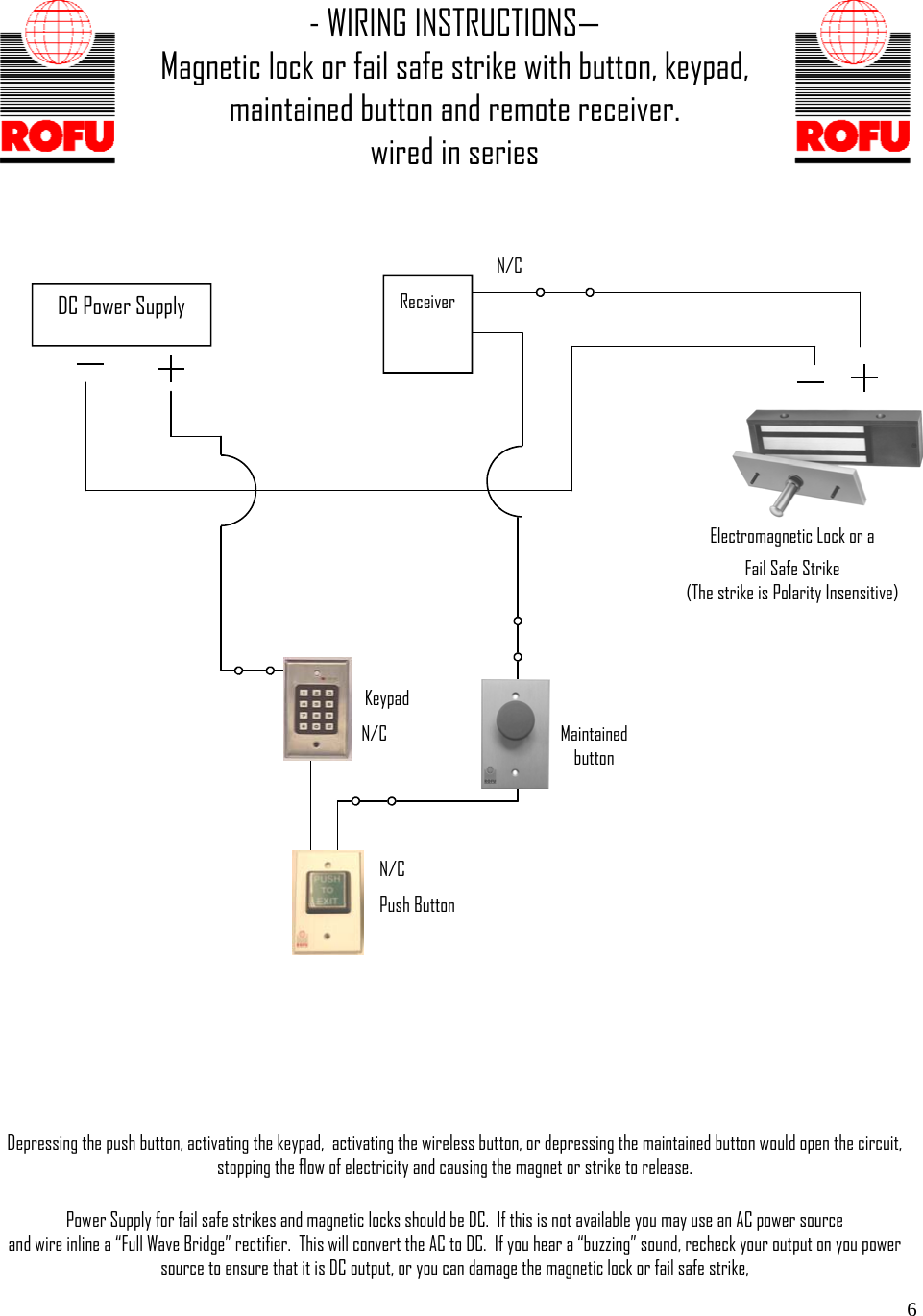
Count the led blinks after turning it. The wire we actually use for the connection is the green one that extends past that blue wire and the power supply socket, as seen in figure 8. Connection diagram door strikes, maglocks, and rex inputs aiphone intercom systems with the door release capability will either activate a built in dry contact or an external relay when the key button is depressed.
These locks include adjustable sec relock time delay and a. After consulting the manual, note which wires will connect to the magnetic lock. Central locking system installation manual actuators installation 1.
Each blink represents 1 second and the counter clockwise recommended time period is 5 seconds (5 blinks). Tighten the electromagnetic lock on the lbracket by using the fixing screw. For single doors locate template against the door and header on the lock jamb side of the frame.
2 adjust the door lock timer for a longer or shorter unlocking time period by turning the screw clockwise. Electrical control panel wiring diagram pdf. Electricity supply, switches, and, of course, locks.
Also make sure that actuator is moving parallel to door lock bolt. Wiring the electromagnetic locking system in the simple diagram above, you can see that the electricity travels in an unbroken loop. The following common wiring diagrams are available:
Wiring diagram for qel panics mag lock wiring diagrams. Even though most electromagnetic locking systems will include other components in the system, the power supply is the one absolutely necessary component for any electromagnetic lock installation, step 1 in design and approval is the wiring diagram. Remove door panels carefully 2.
Surface mount face mount the x value in the table below for each bracket to mount on the door frame, shows the minimum requirement width of the door frame for different electromagnetic lock model. Measure the correct position by bringing the armature plate close to the contact surface of the electromagnetic lock. An example of a wiring diagram for a motor controller is shown in figure 1.
Make sure that the door is still closeable. Diagrams are also useful for trouble shooting and making wiring repairs. Rotate magnet, end blocks and wiring cover as shown, then reassemble.
Find this and other arduino tutorials on arduinogetstarted.com. Wiring cover magnet spacer end block (with screw holes) front side of lock c. 1 find a mounting location on the door frame for the lbracket.
These schematics are also commonly used to confirm the location of wiring and the use of a wiring diagram can ensure the installation is following local building code requirements. Magnetic locks, also referred to as mag locks or maglocks for short, rely on a constant flow of electricity to stay sealed. Push button release electric strike.

31 Door Lock Wiring Diagram Free Wiring Diagram
PI Manufacture

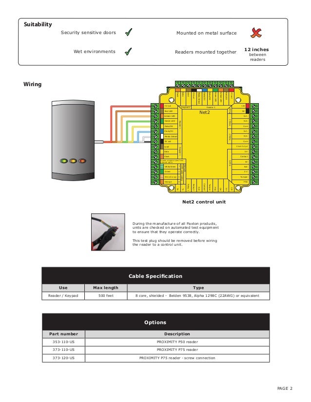
Paxton Door Access Wiring Diagram
31 Door Lock Wiring Diagram Free Wiring Diagram

External Mag Lock Wiring Diagram / Solve The Problem

[CD_1420] Lock Wiring Diagram Ga Single

[CD_1420] Lock Wiring Diagram Ga Single
Paxton Door Access Wiring Diagram
External Mag Lock Wiring Diagram / 31 Hid Card Reader
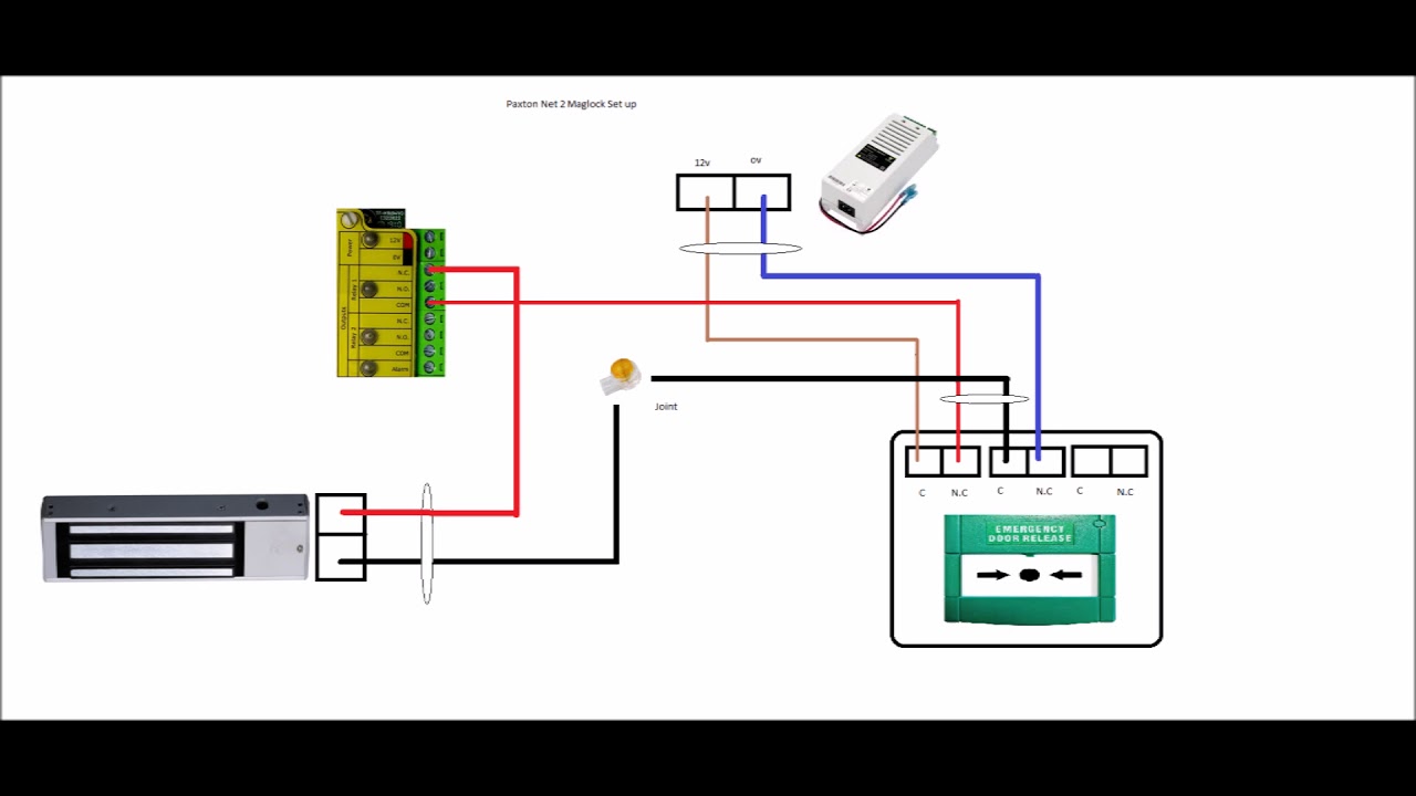
Wiring Diagram For Maglock
External Mag Lock Wiring Diagram / Em Lock Wiring Diagram


Wiring Diagram Of Providing Power To A Fail Safe Maglock
31 Door Lock Wiring Diagram Free Wiring Diagram


31 Door Lock Wiring Diagram Free Wiring Diagram

Wiring Diagram For Maglock
Zkteco K40 Wiring Diagram Wiring Diagram Schemas
Electrical Control Panel Wiring Diagram Pdf Wiring Diagram
31 Door Lock Wiring Diagram Free Wiring Diagram


Em Lock Wiring Diagram Wiring Library